The content of this page has not been vetted since shifting away from MediaWiki. If you’d like to help, check out the how to help guide!
Stack Object Combiner
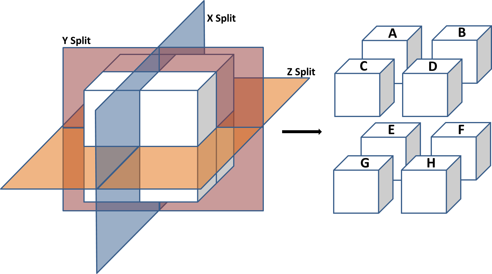
Because of the cubic cost of the 3D segmentation (in memory and processing) with Ilastik, it is not possible to work on full stacks of EM images in once.
To be fully segmented, the stack need to be cut in parts. But this operation will cut some objects in 2 or more parts, and the objects will lost the coordinate system of the original stack.
The purpose of this plugin is to replace the objects in their original position, and provide a tool that will allow a user to merge 3D objects that have been cut.
Installation
Bug with memory watch parameter, increase it so its not a limit for the plugin anymore (higher than what IJ is allowed to have, e.g. 8000 if IJ is allowed to have 8GBytes)
The plugin can be found on the github project in the release tab (please take the lattest version of the plugin).
Download the .jar file and place it in the plugin folder of ImageJ.
This plugin also need the apache common maths librairy. If you use Fiji, this librairy is already included. If you use ImageJ, download the lattest version and put the .jar file into ImageJ/plugins/jars/
Presentation of the interface

Here is the Interface of Stack Object Combiner. The window contain several boxes, that allow you to set the different parameters and that give you an overview of the meshes.
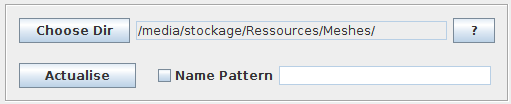 Folder selection box
This is the Folder Box. Choose the folder containing your meshes. To work only with certain meshes inside this folder, use the “Name pattern” function. Write the characters that the file contains, and click on “Actualise”. The pattern can be a Regular expression.
Finally “Actualise” allow you to refresh the folder, for example if you have deleted or added files.
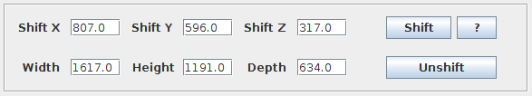 Shift box
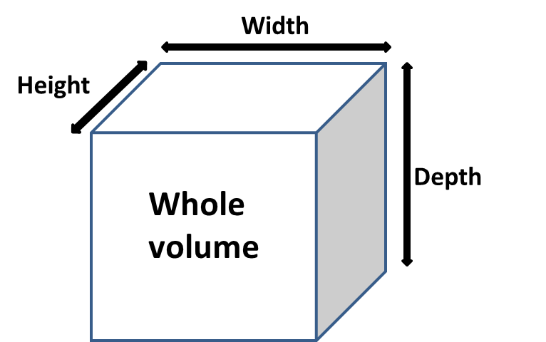
In the shift box, set the positions and dimensions of the cubes. To shift the meshes at their coordinates in the reconstructed volume, give the values of the shift in X, Y and Z. (See the illustration bellow to see to what each value correspond). X, Y and Z correspond respectively to the width, height and depth of the stack A (don’t confuse the width, height and depth of the whole volume that you also have to give here, with the width, height and depth of the volume A that match the values of Shift X, Y and Z).
Once these values are set, click on “Shift” to shift all the meshes listed. To shift back the mesh to their original positions, click on “Unshift”.
The values you give here will be used later to merge the meshes. For automatic merging, you have to give the width, height and depth of the whole volume.
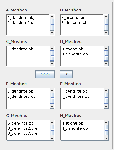 Meshes listing box
In this box, the meshes are placed in the list corresponding to the different volumes. To be listed, the prefix of the mesh name must match the volume name. For example, a dendrite that need to be placed in the A volume can be called A_dendrite.obj (a_dendrite also work). Note that the “_” after the letter is necessary for the object to be recognized by the plugin.
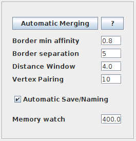 Automatic merging box
This box contain the different parameters to merge the meshes automatically. The parameters correspond to constants inside the plugin, and changing them can help to resolve malfunctioning of the plugin. Here is a description of the different parameters:
- Border min affinity: Range [0 - 1] It is the threshold value above which two meshes have similar properties. In automatic merging mode, the plugin compute for each border of the meshes the perimeter, the volume and the position of the barycentre. A similarity value is computed between the borders. If it’s higher than the parameter, the borders are compatible for merging.
- Border separation: The borders of the meshes have to be decomposed into fragments to be located on only one side of the volume. This parameter help to separate the borders. If the message “Error while separating the borders” appear, increase this parameter.
- Distance window: It is the distance between the vertices of the meshes and the splits. The quality of the border separation can be modified with this parameter.
- Vertex pairing: When two borders are compatible, new faces have to be created. This value represent the size of the sets of vertices combined together. These sets are useful to prevent the formation of aberrant faces between the meshes.
- Memory watch: If the memory available goes bellow this value, the plugin will remove from the memory all the meshes previously processed to make space. But then the plugin will need to reload all the meshes when it will come to the final step. (value in MByte) Bug with this parameter, increase it so its not a limit for the plugin anymore (higher than what IJ is allowed to have, e.g. 8000 if IJ is allowed to have 8GBytes)
Once that the parameters have been set, click on “Automatic merging”. A trace of the merging will appear in the log.
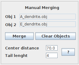 Manual merging box
The manual merging is the older implementation of the plugin. The automatic version should be more efficient and reliable than this version. However if the automatic version don’t properly pair the meshes, using the manual merging can give you different results. The way the borders are detected and paired is different, and with this mode you choose which two objects you want to fuse together.
Here is the description of the parameters:
- Border min affinity: The same as the one used in the automatic version. However here the treshold is applied here only against the length of the borders.
- Center distance: The tolerance for the distance of the centers of the borders (the center is calculated as the mean position of the vertices of the border, and so it is not very reliable). Only applied to circular borders.
- Distance window: The same as the one used in the automatic version.
- Tail length: The number of vertices removed from the ends of a linear borders. Due to the distance to the split, some artefact can appear on the end of the linear borders. This parameter help to fix this.
- Vertex pairing: The same as the one used in the automatic version.
Once the parameters are set, add the meshes you want to fuse. Select them in the list and click on the “>>>” button. You can also use the shortcut “A” to add a mesh highlighted.
Finally click on the “Merge” button or use the shortcut “S”.
Example
During this example, you can look at the different step with the 3DViewer, or with Blender.
- Download the meshes of a mitochondria in the shape of a donut divided in 4 parts MitoDonut Meshes.zip
- Launch the plugin, and give the directory containing the .obj file
- X shift : 192 Y shift : 214 Z shift : 500
- Width : 600 Height : 600 Depth : 600
- Click on the Shift button to shift the meshes.
- Now merge the meshes with the Automatic merging button, or two by two with the manual merging.
- Look at the result
Reference
This plugin haven’t been published yet, but if you want to cite you can always refer to it as T. Boissonnet,”Stack Object Combiner plugin for ImageJ”, https://imagej.net/plugins/stack-object-combiner, October 2015
Contact
For any suggestions, questions, problems or just to give feedback, please feel free to contact Tom Boissonnet at tom.boissonnet@embl.it
Licence
This program is free software; you can redistribute it and/or modify it under the terms of the GNU General Public License as published by the Free Software Foundation (http://www.gnu.org/licenses/gpl.txt).
This program is distributed in the hope that it will be useful, but WITHOUT ANY WARRANTY; without even the implied warranty of MERCHANTABILITY or FITNESS FOR A PARTICULAR PURPOSE. See the GNU General Public License for more details.